Return flow should never be aimed at a fluid intake line. Hydraulic design of baffles in disinfection control tanks.

Part 2 Reservoir Hydraulic Power Pack Basic Hydraulic Pneumatic Hindi English Youtube
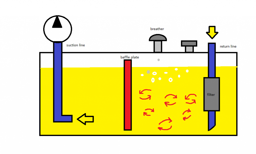
A physical barrier baffle that separates fluid entering the reservoir from fluid entering the pump suction line air space above the fluid to accept air that bubbles out of the fluid access to remove used fluid and contaminants from the system and to add new fluid.
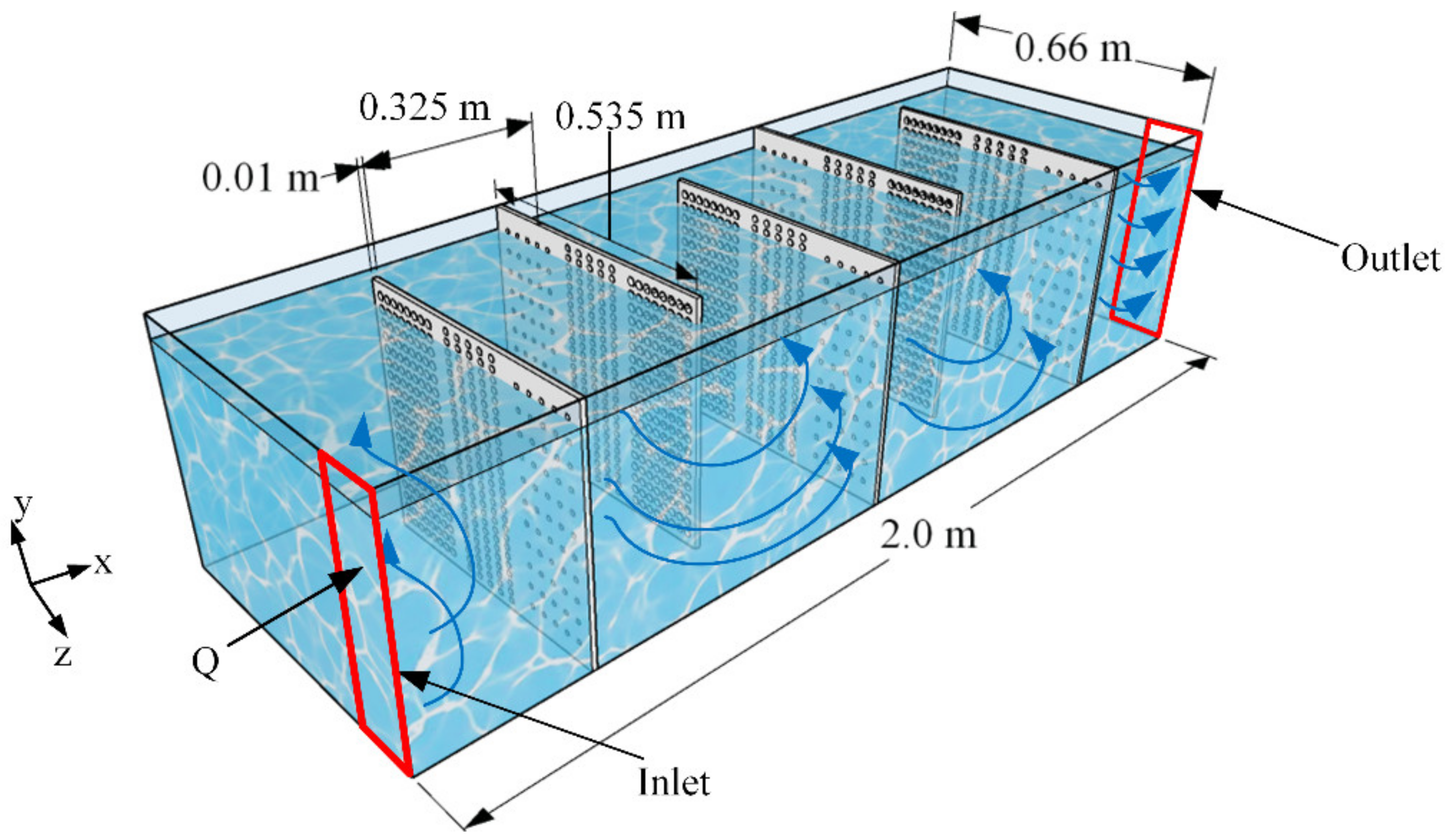
. Several variations of new hydraulic tank designs are compared. It was found that the baffle lengths should be prescribed such that their openings are roughly equal to the width of the tanks channels. 10 Things To Know Before Buying A.
Company standard which has been around for years states that oil passage cutouts have an area at least 2-12 times the total pump inlet area No one can tell me where this requirement came from. VESCOR has always offered exceptional quality and service in the manufacturing of hydraulic reservoirs for a wide variety of applications. In most hydraulic systems the deaeration is solely reached by passive measures.
Baffles work to efficiently separate the return flow from the inlet flow. This allows more heat to radiate as it takes a longer route in the tank. The paper presents the development of industrial 400 litre hydraulic tank.
In this study a perforated baffle design is proposed to improve mixing in contact tanks. The proposed slot-baffle design improves the hydraulic efficiency by 44 mixing efficiency by 42 and reduces the energy required to drive the flow through the system by 43. Diesel Tanks D-Tank Hydraulic System Design and Operation Hydraulic Reservoir Guide Hydraulic Reservoir Tank Industry Connections Further Reading.
7 Solid Reasons Why You Would Choose Propower As Your Tank Supplier. The baffle is a plate or internal shape added to the reservoir to force fluid to travel a longer distance to reach the suction port. Journal of Hydraulic ResearchDe Recherches.
Ad Improving Water Treatment Tank Performance. BAFFLE DESIGN Baffles direct diffuse and contain fluid and increase tank stiffness. The amount of oil in the hydraulic tank is typically much more than the volume needed for the operation of asymmetric actors like hydraulic cylinders.
Additionally baffles help the reservoir fluid circulate which promotes heat dissipation from the fluid. NPT suction returnports at the bottom of each end of the tank and a 12 in. Configuration by altering channel width baffle length and flow orientation.
Figure 1 To help cool return fluid it should be directed toward the outer walls of the reservoir. Hydraulic Tank Baffle Design natebott Mechanical OP 2 May 06 1521 Looking for rules of thumb on baffle design for hydraulic tanks. Hydraulic tank design is often neglected part of the development.
In an effort to address this question a carefully conceived parametric study consisting of 30 high-resolution two-dimensional planar simulations was conducted to quantify the hydraulic. In this manner excessive constrictions or expansions which lead to undesirable flow separation can be prevented. In order to reduce oil swirling and improve stability of fluid flow CFD simulations of oil flow inside hydraulic tank were made.
The reservoir should have internal baffles to reduce sloshing and to prevent the hot returning oil from immediately entering the pumps intake port. A good hydraulic reservoir should have internal baffles situated in such a way that they prevent return line air from being drawn into the pump inlet. Hydraulic reservoirs and accessories.
Improve flow patterns in circular and rectangular tanks. To help cool return fluid it should be directed toward the outer walls of the reservoir. H Water depth L Length of the flocculator channel S Space between baffles T Thickness of the baffles B Perpendicular center to center distance between baffles ST B H L S 15S 15 SUpper baffle Lower baffle Minimum water level Port from previous channel Exit to the sedimentation tank entrance channel Design Considerations.
Turbulent flow through the perforated baffle is studied at the perforation hole scale. Baffles direct diffuse and contain fluid and increase tank stiffness Fig. Because the baffle forces fluid to remain in the tank longer more time is given to settle out water and particles.
NPT portdrain on the tank bottom. 10 Things To Know Before Buying A Fuel Tank. The contribution of jets emerging from the perforations to the mixing process is evaluated in terms of standard mixing indexes for various perforation parameters such as the solidity ratio and hole.
While offering a compete line of standard reservoirs VESCOR is one of the largest manufacturer of customized tanks and reservoirs. Such designed solutions are baffles to direct the flow or wire-gau zes to hold back air bubbles. The cylinder design and aluminum construction can match your trucks fuel tank for a balanced finished appearance.
Hydraulic System Design Operation. Never rework a fuel tank into a hydraulic tank. The fluid should also flow across magnets which intercept ferrous particles.
The fluid should also flow across magnets provided to intercept ferrous particles. The reservoir includes 2 in. It features a durable 11 Ga aluminum shell and 12 Ga heads.
H Carlston J Venayagamoorthy S.

Hydraulic Reservoirs Fluidsys Training Centre
Hydraulic Tank Design And Work Basic Stuffworking Com
2

Novel Slot Baffle Design To Improve Mixing Efficiency And Reduce Cost Of Disinfection In Drinking Water Treatment Journal Of Environmental Engineering Vol 143 No 9

Why The Tank May Well Be A Hydraulic Fluid S Best Friend
Taking A Deep Dive Into The Hydraulic Reservoir
Water Free Full Text A Perforated Baffle Design To Improve Mixing In Contact Tanks

Industrial Hydraulics Design Hydraulic Reservoir Design
0 comments
Post a Comment